I joined the Duke Aeroelasticity Lab in Summer 2021 under the supervision of Professor Earl Dowell; I studied the buckling of vertical cantilevered plates under corner twisting loads. This work was published in the Journal of Applied Mechanics. The counterintuitive buckling mode was first found theoretically by Pai et al. We replicated the finite element results by Pai for comparison with experimental data. Unlike many common buckling modes, the corner loads will cause nonlinear out of plate deformations and buckling always occurs in the nonlinear range. Due to the nonlinear behavior we were interested in deformations before, during, and after bucking. I focused on experimental test design and data collection for comparison with finite element result data. Data was gathered from three distinct rectangular plates made of 6061 aluminum alloy, each with different widths and aspect ratios.
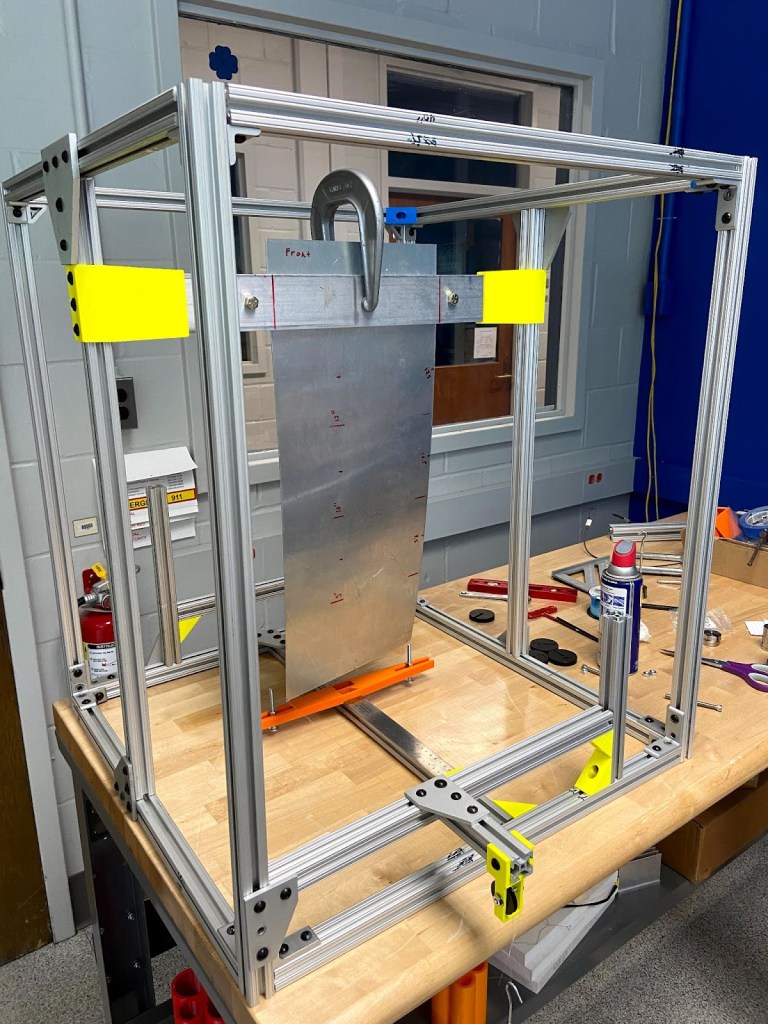
The test apparatus was built using 1-inch thick 80/20 aluminum t-slot extrusions, fixed together with a mix of 3D-printed PLA and standard metal t-slot brackets to form a prismatic structure. Attached to this setup were a clamp, a ruler, and two low-friction acetal plastic pulleys. A test plate could be placed into the clamp, which consisted of two 2.5-inch wide 6061 aluminum bars bolted on each side of the plate, with an additional C-clamp in the middle for even pressure distribution. The maximum plate length accommodated within the extended rig was 35 inches, setting an upper limit on aspect ratios. The clamping mechanism allowed for the testing of one plate at a range of different aspect ratios. Comparing the results of one plate at various aspect ratios was crucial because slight curvatures in a plate would effect deformations and make comparison between plates difficult.
Monofilament fishing line was tied to small holes in the corner of the plate and wrapped over pulleys to apply gravity loads to the corners with hanger masses. The displacement of the plate is influenced by how mass is added or removed, with a gradual addition recommended to mimic a quasi-static load increase and avoid dynamic disruption to the system. Controlling the direction of buckling is possible by adding mass preferentially to one side, with the practice of always adding mass to the intended buckling side first and removing it last. Due to pulley friction, there exists a limited range of equilibrium displacements for each corner, with dynamic disturbances potentially causing the corner to settle at various positions within this range, typically varying by about a centimeter. I worked to develop a measurement technique to consistently capture the maximum displacement on the buckled side. Initially, adding load to one side will push the buckled corner beyond its equilibrium displacement, but slowly equalizing the load by adding mass to the other side will return the corner to its maximum equilibrium displacement. Capturing the maximum displacement limited uncertainty and allowed for consistent data collection across different aspect ratios.

The video above illustrates the two buckling modes that were observed as the plate is forced by hand between the two positions.
Corner displacements were measured via a 3D printed ruler jig which had an uncertainty of +/-3 mm. Friction within the pulley resulted in corner load uncertainty. The pulleys were measured to contribute about 0.1 N of internal friction contributing to load uncertainty.
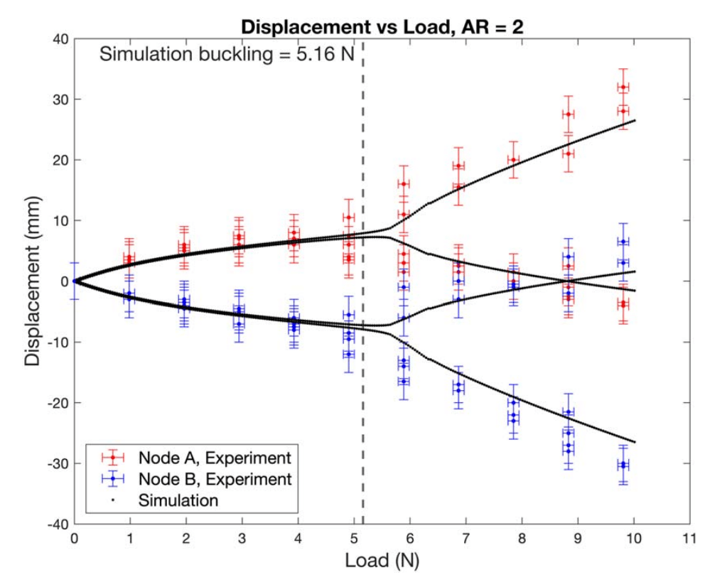
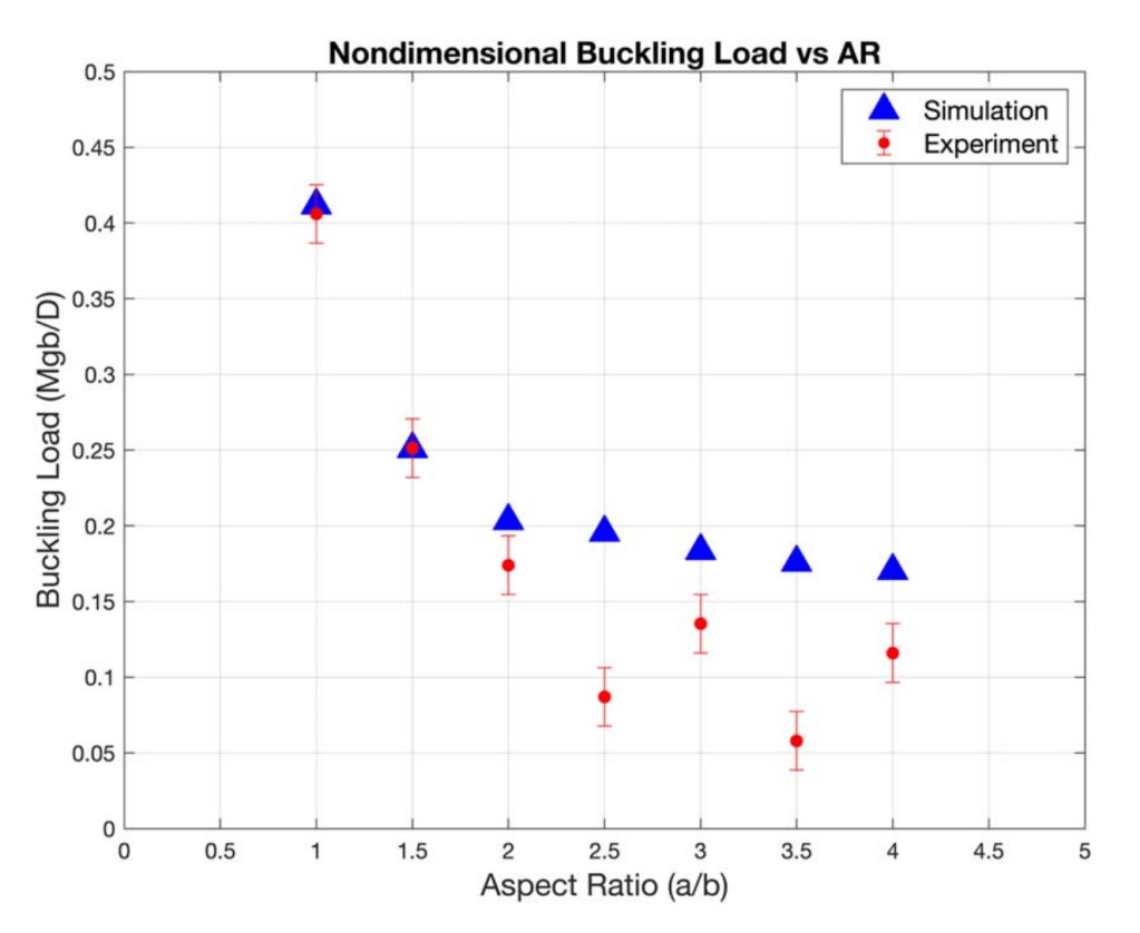
The computational results, produced by Oliver Gibson, agreed well with the experimental data, particularly at low aspect ratios. Higher aspect ratio plates tended to be more sensitive to deformation and have high uncertainty. This is seen best when comparing the buckling load to the aspect ratio – the simulated buckling load approaches an asymptote as aspect ratio increases while the experimental data has large variations.